CHAPTER 1
INTRODUCTION
Gas leakage is the major problem with industrial sector, residential milieu and gas functioning vehicles like CNG (Compressed Natural Gas) buses, cars etc. Bhopal gas tragedy was an example of gas leakage accident in India which is a world’s worst industrial disaster.
Gas leakage stopping has importance as gas leakage detection has.This paper provides a cost effective and highly accurate system,which not only detect gas leakage but also alert (Beep),send an SMS and switch on the exaust fan to decrease the gas density by taking out into environment. GSM module is used which alert the user by sending an SMS. In order to provide high accuracy MQ-6 gas sensor has been used.
Liquefied Petroleum Gas is consists of Butane and Propane gases, which are highly inflammable in nature. The LPG is an odorless gas and but the addition of Ethanethiol allows it to exhibit an odor during its leakage. An ideal gas sensor can sense the leakage of an LPG from vehicles, industries, homes and other residential areas. If there is a leakage of LPG, we can easily identify by its concentration through the gas sensor and by means of rise in temperature. The LPG is widely used for domestic purposes such as heating, boiling and cooking. Some people may have a low sense of smell and in such cases they may not be able to respond for presence of the gas concentration. Thus, a security based LPG detection system is essential to provide alertness, safety and security from any harmful gas leakage accidents.
This leakage detection system senses the gas leakage and also stops the gas supply along with an alarm,a GSM alerts the specified user and turns on the exaust fan.The gas sensor we used here also sences the presence of toxic gases apart from LPG.The gas sensor output voltage goes LOW when there is a leakage of any toxic gas.This LOW signal is sent to a microcontroller which in turn sends those signals to the buzzer hence, rising an alarm.
After a few milliseconds, the gas leakage message is sent to the user registered mobile number in microcontroller via GSM module. The microcontroller continues to send the message vis GSM module until the gas level is decreased to below the threshold level which is already fixed in microcontroller.
The problem to be solved in this project work is:
1.4 Organization of the Thesis
Chapter1Gives introduction about the motivation, objective of the project, problem statement and thesis of the organization.
Chapter2 Deals with literature survey on LPG Gas detection by using AVR Micro Controller
Chapter3 Deals with the methodology and technology involved in the designing of LPG Gas detection by using AVR Micro Controller
Chapter4 Gives introduction and concerned details about the assembly Language and Keil Software.
Chapter5 Deals about result analysis.
Chapter6 Deals with conclusion and future scope of the project.
CHAPTER 2
LITERATURE SURVEY
2.1 Introduction
Various research teams are working everywhere for the development of Microcontroller primarily based LPG Gas Leakage Detectors using GSM Module. LPG, first produced in 1910 by Dr. Walter Snelling.It is a mixture of Commercial Propane and Commercial Butane having saturated and unsaturated hydrocarbons. In the 1980s and 90s, Before the development of electronic household gas detectors gas presence was detected with a chemically infused paper which changes its colour when it is exposed to the gas. Since then, various technologies and devices have been developed to detect, monitor, and alert the leakage of gases various fields.
The main applications of a LPG Gas Leakage Detector would be :
This project has many advantages which are as follows:
This Project has a lot of Future Scope in the sense that we can provide a voice feedback system in the future by using this project. With recent advancements in technology, Temperature show during times whereby no message buffers are empty is one such theoretical improvement that’s well possible. Another interesting and vital improvement would be to accommodate multiple receiver MODEMS at completely different positions within the geographical region carrying duplicate SIM cards. Multilingual display can be another added in the project. To make it user friendly Audio output can be introduced to this project.
CHAPTER 3
HARDWARE IMPLEMENTATION OF LPG GAS DETECTION
3.1 Project Explanation
The project principally concentrates on recognizing the nearness of hazardous LPG gas spillage in the autos, benefit stations or in the capacity tank condition utilizing the perfect gas sensor. This unit can be effectively incorporated into a different unit that can sound a caution or give a visual sign of the LPG focus. The sensor has both fast reaction time and outstanding affectability. This sensor can likewise be utilized to detect couple of different gasses like isobutane, propane, LNG and even tobacco smoke.
The LCD show demonstrates the convergence of the gas. The yield of the gas sensor goes low when the LPG sensor detects any gas spillage from the capacity. If there should arise an occurrence of any spillage in the gas, sensor yield is given to the microcontroller and afterward the fumes fan is turned ON. GSM module keeps on sending message to the client as ‘Gas spillage recognized’ to the pre-characterized versatile number until the measure of gas is lessened beneath he limit level.
3.1.1 Hardware Used
3.1.2 THEORY OF OPERATION:
In TGS gas sensors, one of the detecting material is a metal oxide, most ordinarily SnO2. The oxygen on the precious stone surface gets adsorbed with a negative charge when the metal oxide gem, for example, SnO2 is warmed at a specific temperature in air. The benefactor electrons on the precious stone surface are then exchanged to the adsorbed oxygen which brings about leaving positive charges in the space charge layer. Therefore the surface potential fills in as a potential hindrance against the stream of electrons.
The electric current streams in the sensor through the mix parts (grain limit) of SnO2 miniaturized scale precious stones. The oxygen which is adsorbed frames a potential boundary at the grain limits which avoids bearers to move unreservedly. The electrical resistance of the sensor is perceived by this potential obstruction. The surface thickness of the contrarily charged oxygen diminishes within the sight of the deoxidizing gas which lessens the hindrance stature in the grain limit. This lessened boundary stature diminishes the sensor resistance.
3.2 BLOCK DIAGRAM
 Figure 3.1 Block Diagram
It is the heart of the project. It is used to control the exhaust fan, LCD display and buzzer when LPG leakage occurs. The I/O ports of the microcontroller are used for this purpose.
This sensor is used to sense the leakage of LPG. In normal conditions, the output of this sensor is HIGH and it goes LOW when the LPG is sensed.
The LPG is pushed put into the environment using an exhaust fan which reduces the concentration of the LPG near the leakage area.
The LCD displays the present concentration of the LPG gas surrounding the sensor.
3.3.1 MQ-5 Gas Sensor :
The Grove – Gas Sensor (MQ5) module is useful for gas leakage detection (in home and industry). It is suitable for detecting H2, LPG, CH4, CO, Alcohol. Due to its high sensitivity and fast response time, measurements can be taken as soon as possible. The sensitivity of the sensor can be adjusted by using the potentiometer.
This is an Analog output sensor. This needs to be connected to any one Analog socket in Grove Base Shield. It is possible to connect the Grove module to Arduino directly by using jumper wires by using the required connections. The output voltage from the Gas sensor increases when the concentration of gas increases. Sensitivity can be adjusted by varying the potentiometer.
The sensor value only reflects the approximated trend of gas concentration in a permissible error range, it DOES NOT represent the exact gas concentration. The detection of certain components in the air usually requires a more precise and costly instrument, which cannot be done with a single gas sensor.
Resistance estimation of MQ-5 is distinction to different sorts and different focus gasses. Along these lines, When utilizing this segments, affectability modification is extremely important. At the point when precisely measuring, the best possible caution point for the gas identifier ought to be resolved in the wake of considering the temperature and stickiness impact.
3.3.1.1 Pin Configuration

Table 3.1 Pin Configuration Figure 3.2 Pin configuration of MQ-
3.3.1.2 Features
3.3.1.3 Specifications
| Symbol | Parameter Name | Technical Condition | Remarks |
| VC | Circuit Voltage | 5v±0.1 | AC or Dc |
| VH | Heating Voltage | 5v±0.1 | AC or Dc |
| PL | Load Resistance | 20kΩ | |
| RH | Heater Resistance | 31±10% | Room temp |
| PH | Heating Consumption | <800mW |
Table 3.2 Specifications
3.3.1.4 Applications
These sensors are used in gas leakage detecting equipment in home and industry appliances, are suitable for detecting LPG, natural gas, town gas, avoid the noise of alcohol and cookery fumes and cigarette smoke.
The AT89S52 is a low-control, elite CMOS 8-bit small scale controller with 8Kbytes of in-framework programmable Flash memory. The gadget is produced utilizing Atmel’s high-thickness nonvolatile memory innovation and is perfect with the business standard 80C51 miniaturized scale controller. The on-chip Flash enables the program memory to be reinvented in-framework or by a traditional nonvolatile memory software engineer. By joining an adaptable 8-bit CPU with in-framework programmable glimmer one solid chip; the Atmel AT89S52 is an intense miniaturized scale controller, which gives an exceedingly adaptable and financially savvy answer for some installed control applications.
3.3.2.2 Features:
• Power-off Flag
• Compatible with MCS-51Products
• Watchdog Timer
• Fully Static Operation: 0 Hz to 33 MHz
• Interrupt Recovery from Power-down Mode
• Endurance is 1000 Write orErase Cycles
• 4.0V to 5.5V is the Operating Range
• Eight Interrupt Sources
• 8K Bytes of In-System Programmable (ISP) Flash Memory
• 32 Programmable I/O Lines
• Three-level Program Memory Lock
• 256K Internal RAM
• 3 16-bit Timer/Counters
• Full Duplex UART Serial Channel
• Low-power Idle and Power-down Modes
• Double Data Pointer

Figure 3.3 Architecture
3.3.2.4 Pin Configuration

Figure 3.4 Pin Configuration of AT89S52 MicroController
The AT89S52 gives the accompanying standard elements: 8K bytes of Flash, 256 bytes of RAM, 32 I/O lines, Watchdog clock, two information pointers, three 16-bit clock/counters, full duplex serial port, on-chip oscillator, and clock hardware. Also, the AT89S52 is planned with static rationale for operationdown to zero recurrence and backings two programming selectable power sparing modes. The Idle Mode stops the CPU while permitting the RAM clock/counters, serial port, and intrude on framework to keep working. The Power-down mode spares the RAM substance yet solidifies the oscillator, incapacitating all other chip capacities until the following hinder or equipment reset.
The Microchip Technology Inc. MCP3001 is a progressive guess 10-bit A/D converter (ADC) with locally available specimen and hold hardware. The gadget gives a solitary pseudo-differential info. Differential Nonlinearity (DNL) and Integral Nonlinearity (INL) are both determined at ±1 LSB max. Correspondence with the gadget is done utilizing a basic serial interface perfect with the SPI convention. The gadget is fit for test rates up to 200 ksps at a clock rate of 2.8 MHz. The MCP3001 works over an expansive voltage extend (2.7V – 5.5V). Low present plan grants operation with an average standby current of just 5 nA and a run of the mill dynamic current of 400 µA. The gadget is offered in 8-stick PDIP, MSOP, TSSOP and 150 mil SOIC bundles.
3.3.3.1 Pin Configuration
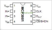
Figure 3.5 Pin Configuration of MCP 3001
3.3.3.2 Features
• 8-pin PDIP, SOIC, MSOP and TSSOP packages
• On-chip sample and hold
• SPI™ serial interface (modes 0,0 and 1,1)
• Single supply operation: 2.7V – 5.5V
• ±1 LSB max INL
• Industrial temp range: -40°C to +85°C
• 200 ksps sampling rate at 5V
• Low power CMOS technology – 5 nA typical standby current, 2 µA max – 500 µA
• ±1 LSB max DNL
• 10-bit resolution
3.3.3.3 Timing Diagram
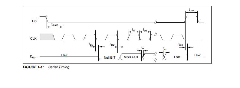 Figure 3.6 Timing Diagram of MCP3001
Fluid Crystal Display screen is a generally utilized electronic show module which had an extensive variety of uses. A 16×2 LCD show is an exceptionally fundamental module and is most ordinarily utilized as a part of different circuits and gadgets. These modules are favored over the 7 sections and other multi-fragment LEDs. One of the reason is being that LCDs are effortlessly programmable, efficient, have no restrictions of showing some exceptional and custom characters, activitys et cetera.
A 16×2 LCD implies it can show 16characters for each line and there are 2 such lines. In this specific LCD each character is shown in the measure of 5×7 pixel network. It has 2 registers viz., information and charge. The capacity of the summon enlist is to store the order guidelines given to the LCD. For the most part charge is a guideline given to LCD to do a particular errand like setting the cursor position, clearing screen, instating it, controlling the show, and so on. The capacity of the information enlist is to store the information to be shown on the LCD screen. The information is put away as ASCII estimation of the character to be shown on the LCD.
LCDs have extensive variety of utilizations, for the most part they are utilized as a part of open air signage, flying machine cockpit shows, instrument boards, TVs, and indoor and PC screens. Little LCD screens are exceptionally regular in acclaimed convenient buyer gadgets, for example, computerized cameras, watches, mini-computers, and cell phones, including cell phones. LCD screens are likewise utilized on customer gadgets items, for example, DVD players, computer game gadgets and timekeepers. LCD screens have supplanted overwhelming, massive cathode beam tube (CRT) shows in almost all applications. LCD screens are accessible in a more extensive scope of screen sizes than CRT and plasma shows, with LCD screens accessible in sizes extending from modest computerized watches to tremendous, extra large flat screen TV sets.
Since LCD screens don’t utilize phosphors, they don’t endure picture copy in when a static picture is shown on a screen for quite a while (e.g., the table edge for an airplane plan on an indoor sign). LCDs are, nonetheless, defenseless to picture persistences.The LCD screen is more vitality proficient and can be discarded more securely than a CRT can. Its low electrical power utilization empowers it to be utilized as a part of battery-controlled electronic gear more productively than CRTs can be. By 2008, yearly offers of TVs with LCD screens surpassed offers of CRT units around the world, and the CRT ended up noticeably out of date for generally purposes.
• B/L to be driven by pin 1, pin 2 or pin 15, pin 16 or A.K (LED)
• 1/16 duty cycle
• N.V. optional for + 3V power supply.
• 5 x 7 dots with cursor
• + 5V power supply (Also available for + 3V)
• Built-in controller (KS 0066 or Equivalent)

Fig 3.7 Pinout of LCD Display
3.3.5 GSM Module
GSM (Global System for Mobile interchanges) is a cell system, which implies that cell phones associate with it via hunting down cells in the prompt region. GSM systems work in four diverse recurrence ranges. Most GSM systems work in the 900 MHz or 1800 MHz groups. A few nations in the Americas utilize the 850 MHz and 1900 MHz groups in light of the fact that the 900 and 1800 MHz recurrence groups were at that point distributed. The rarer 400 and 450 MHz recurrence groups are alloted in a few nations, where these frequencies were already utilized for original frameworks. GSM-900 utilizations 890–915 MHz to send data from the portable station to the base station (uplink) and 935–960 MHz for the other course (downlink), giving 124 RF channels (channel numbers 1 to 124) separated at 200 kHz. Duplex dividing of 45 MHz is utilized. In a few some countries the GSM-900 band has been extended to hide a bigger frequency range. This ‘extended GSM’, E-GSM, uses 880–915 MHz for uplink and 925–960 MHz for downlink, adding fifty channels the channel numbers 975 to 1023 and 0 to the primary GSM-900 band. Time division multiplexing is utilized to allow eight full-rate or sixteen half-rate speech channels per radio frequency channel. There are eight radio timeslots giving eight burst periods classified into what is referred to as a TDMA frame. Half rate channels use alternate frames inside an equivalent timeslot. The channel rate is 270.833 kbps, and thus the frame duration is 4.615ms
3.3.5.1 Advantages:
GSM also pioneered a cheap , to the network carrier, different to voice calls, the Short message service (SMS, also referred to as “text messaging”), that is currently supported on different mobile standards also. Another advantage is that the standard includes one worldwide Emergency number, 112. This makes it easier for international travelers to attach to emergency services whereas not knowing the native emergency range
3.3.5.2 The GSM Network
GSM provides recommendations, not needs. The GSM specifications outline the functions and interface needs thoroughly however don’t address the hardware. The GSM network is split into 3 major systems: the switching system -SS, the base station system -BSS, and the operation and support system-OSS.

Figure 3.8 GSM Network
.3.3.5.4 The Base Station System (BSS):
All radio-related functions are performed in the Base Station System, that consists of base station controllers -BSCs and also the base transceiver stations BTSs.
• BSC: The BSC provides all the required control functions and physical links which are essential between the MSC and BTS. it’s a high-capacity switch that has functions like hand over, cell configuration data, and management of radio frequency power levels in the base transceiver stations. A number of BSCs are served by MSC.
• BTS: This handles the radio interface to the mobile station. The BTS is the the radio equipment (transceivers and antennas) required to service every cell within the network. A group of BTSs are controlled by a BSC.
This is connected to all equipments within the switching system and to the BSC. The implementation of OMC is termed the operation and support (OSS). The OSS is the functionl entity from that the network operator monitors and controls the system. The Purpose of this is to offer the customer cost-effective support for centralized, regional and native operational and maintenance activities that are needed for a GSM network. A crucial function of OSS is to provide a network summary and support maintenance activities of various operation and maintenance organizations.
• Message center (MXE): The MXE is a node that gives integrated voice, fax, and data messaging. Specifically, the MXE handles short message service, cell broadcast, voice mail, fax mail, e-mail, and notification.
• Mobile service node (MSN): The MSN is that the node that handles the mobile intelligent network (IN) services.
• Gateway mobile services shift center (GMSC): The GMSC is a node used to interconnect two networks. The Gate way is usually implemented in associated MS. The MS is then stated to as GMSC.
• GSM inter-working unit (GIWU): The GIWU consists of each hardware and a software that has an interface to numerous networks for data communications
3.3.5.7 Specifications
Specifications for various personal communication services (PCS) systems vary among the PCS networks.The specifications and characteristics for GSM are shown below.
• Frequency band: The frequency range specified for GSM is 1,850 to 1,990 MHz from mobile station to base station.
• Duplex distance: The simultaneous transmission at both the ends distance is 80 MHz. Duplex distance is that the distance between the uplink and downlink frequencies. A channel has 2 frequencies, 80MHz apart.
• Channel separation: The separation between side by side carrier frequencies is 200 kHz in GSM.
• Modulation: Modulation is the process of sending a signal by changing the characteristics of a carrier frequency. This is done in GSM via Gaussian minimum shift keying (GMSK).
• Transmission rate: GSM is a digital system with an over-the-air bit rate of 270 kbps.
• Access method: GSM uses the time division multiple access concept. TDMA is a technique inwhich many different calls could share constant carrier. every call is assigned a particular timeslot.
• Speech coder: GSM uses linear predictive coding(LPC). The purpose of LPC is to decrease the bit rate. The LPC is the one which provides parameters for a filter that mimics the vocal tract. The signal passes through this filter, leaving a residual signal. Speech is encoded at 13 kbps.
3.3.5.8 GSM Subscriber Services
Dual-tone multi-frequency (DTMF): DTMF is a tone signalling technique which used for various control purposes via., the telephone network, such as remote control for answering machine. GSM supports full-originating DTMF.
Facsimile cluster III: GSM provides a support for CCITT group 3 facsimile. As standard fax machines are simply designed to be connected for a telephone using analog signals, a special fax device connected to the exchange is employed within the GSM system. This allows a GSM–connected fax to communicate with any analog fax within the network.
Short message services: A suitable facility of the GSM network is that the short message service. A message consisting of a most of one hundred sixty alphanumeric character set characters will be sent to or from a mobile station. This service will be viewed as a advanced form of alphanumeric paging with variety of benefits. If the subscriber’s mobile is switched off or has left the coverage area, the message will be stored and offered back to the subscriber once the mobile is switched on or has reentered the coverage area of the network. This function confirms that the messages are received.
Cell broadcast: A variation of the short message service is that the cell broadcast facility. A message of a most of ninety three characters can be broadcast to all any mobile subscribers in a bound geographical area. Vital applications include traffic congestion warnings and reports on accidents.
Voice mail: Voice mail is truly answering machine in the network,that is controlled by the subscriber. Calls will be forwarded to the subscriber’s voice-mail box and also the subscriber checks for messages via a private security code.
Fax mail: In this the subscriber can receive fax messages at any fax machine. The messages are stored during a service center from that they will be retrieved by the subscriber via a private security code to the required fax number.
3.3.5.9 Main AT commands
AT command set for GSM Mobile Equipment elaborates the Main AT commands for the purpose of communication via a serial interface with that of GSM subsystem of the phone.
AT commands are generally used for controlling a modem. AT is an abbreviation of Attention/Application Terminal. Every AT command line begins with an “AT” or “at”so these commands are called AT commands. Most of these commands that are utilised and contains commands such as ATD for Dial, ATA for Answer, ATH for Hook control and ATO for Return to online data state, are also used by GSM/GPRS modems and mobile phones. Besides this common AT command set, GSM/GPRS modems and mobile phones which supports an AT command set that is specific to the GSM technology includes SMS-related commands like AT+CMGS for SMS message sending, AT+CMSS for Send SMS message from the storage, AT+CMGL possess the List SMS messages and AT+CMGR are widely used for the purpose of Read SMS messages.
Note that at the beginning of “AT” is the prefix which informs the modem about the beginning of a command line. It is not related to the AT command name. For example, D is an original AT command name in ATD and +CMGS is the original AT command name in AT+CMGS. However, some books and different web sites use them as the name of an AT command.
Here there are some of the tasks that can be easily achieved utilizing AT commands with a GSM/GPRS modem or mobile phone any where.
3.3.6 MAX 232
A standard serial interface for PC, RS232C, utilizes negative logic, i.e., logic 1 is -3V to -12V and logic 0 is +3V to +12V. To convert TTL logic, TxD and RxD pins of the microcontroller requires a converter chip. A MAX232 chip was utilized in many micro controllers boards. It is a dual RS232 receiver / transmitter that coincides all RS232 specifications while using only +5V power supply. It possess two onboard charge pump voltage converters which generate +10V to -10V power supplies from a single 5V supply. It possess four level translators, two of which are RS232 transmitters that convert TTL/CMOS input levels into +9V RS232 outputs. The other two level translators are RS232 receivers that convert RS232 input to 5V. The MAX232 circuit is shown below.


Figure 3.9 Pin Configuration of MAX232 Figure 3.10 MAX232
3.3.6.2 Features
1. Operates With Single 5-V Power Supply
2. LinBiCMOSE Process Technology
3. Two Drivers and Two Receivers
4. ±30V Inputs.
5. Low Supply Current -8 mA typical.
6. Meets TIA/EIA-232-F Recommendation
7. Designed for exchangeable With Maxim MAX232
8. ESD Protection can Exceeds 2000 V Per MIL-STD-883,the Method 3015
9. Package Options which Includes Plastic Small-Outline (D, DW) Packages and Standard Plastic (N) DIPs.
A standard serial interfacing for PC, RS232C, uses negative logic, i.e., logic ‘1’ is -3V to -12V and logic ‘0’ is +3V to +12V. To convert a TTL logic, TxD and RxD pins of the µC chips, thus requires a converter chip. A MAX232 chip used in many µC boards. It provides 2-channel RS232C port and requires external 10µF capacitors. Carefully check the polarity of capacitor when soldering . A DS275 however, does not require external capacitor and smaller. Either of the circuit can be used without any problems.

Figure 3.11 Circuit Interfacing connections

Figure 3.12 Circuit Interfacing connections
3.3.6.4 Applications

Figure 3.13 Power Supply Circuit

Figure 3.14 Fan And Buzzer Interconnection

Figure 3.15 LCD Display Interconnection

Figure 3.16 GSM Module Interconnection Using MAX232
CHAPTER 4
SOFTWARE IMPLEMENTATION OF LPG GAS DETECTION
This is a brief note on the assembly language. Assembly language is the basic programming language available for any processor , controller . With assembly language, a programmer can perform the operations directly on physical CPU. Assembly language lacks high-levels such as variables and functions, and it is not same for various families of processors .The assembly language is the most powerful processor programming language available, and it gives programmers an idea needed to write effective code in the high-level languages. Learning assembly language is quite much useful to an every serious programmer.
Before we looking at the process of writing computer programs, we have to get brief idea about the basics and learn what exactly a computer is and how it will works. Every computer, no matter how simple has at its exactly two things: a CPU and memory. these two things are important for your computer to run programs.
On the most crucial level, a PC program is simply gathering of numbers put away in memory. Different numbers advise the CPU to do distinctive things. The CPU peruses the numbers each one in turn, unravels them, and does what the numbers say. For instance, if the CPU peruses the number 64 as a component of a program, it will add 1 to the number put away in an uncommon area called AX. On the off chance that the CPU peruses the number 146, it will swap the number put away in AX with the number put away in another area called BX. By joining numerous basic operations such these into a program, a software engineer can make the PC perform numerous mind boggling things.
As an example, here are some numbers of a straightforward pc program: 184, 0, 184, 142, 216, 198, 6, 158, 15, 36, 205, 32. If you wish to enter these numbers into your computer’s memory and run them below Microsoft disk operating system, you’ll see a greenback sign placed within the lower corner of your screen, that’s what these numbers tell the computer to do.
In spite of the fact that the quantities of the above program sound good to a PC, they are about as unintelligible to a human. Who might have speculated that they put a dollar sign on the screen? Plainly, entering numbers by hand is a lousy approach to compose a program.
It doesn’t need to be like this, however. Quite a while back, somebody concocted the possibility that PC projects could be composed utilizing words rather than numbers. An extraordinary program called an assembler would then take the software engineer’s words and change over them to numbers that the PC could get it. This new strategy, called composing a program in assembly language, spared software engineers a huge number of hours, since they no longer needed to look into difficult to-recall numbers in the backs of programming books, however could utilize basic words.The program which is written above, written in assembly language, looks like this:
MOV AX, 27104
MOV DS, AX
MOV [4226], 36
INT 32
When an assembler interprets this sample program, it converts each line of program into one CPU-level instruction. This program utilizes two types of instructions, MOV and INT. On Intel processors, the MOV instruction moves data , while the INT instruction transfers processor control to the device drivers.
The program not exactly certain still, however it is significantly less demanding to comprehend than it was some time recently. The main direction, MOV AX, 27104, advises the PC to duplicate the number 47104 into the area AX. The following direction, MOV DS, AX, advises the PC to duplicate the number in AX into the area DS. The following guideline, MOV [3998], 36 advises the PC to put the number 36 into memory area 3998. At last, INT 32 exits the program by coming back to the operating system.
We should simply ahead and run this program. To start with, make sure to print these instructions out, since you should allude to them as we go on. Next, tap on your start menu, and run the program called MS-DOS Prompt. A dark screen with white text ought to show up. We are currently in MS-DOS, the way PCs used to be 20 years prior. MS-DOS was before the times of the mouse, so you should sort commands on the console to make the PC get things done
To start with, I need you to sort the word debug, and press enter. The cursor ought to move down a line, and you ought to see the Debug incite, which is a simple dash. We are currently in a program called Debug. Debug is an intense utility that lets you straightforwardly get to the registers and memory of your PC for different purposes. For our situation, we need to enter our program into memory and run it, so we’ll utilize Debug’s an order, for assemble. Simply ahead and sort a100 now. The cursor will move down a different line, and you can observe something like 1073:0100. This will be the memory location we will enter low level computing construct instructions at. The primary number is the segment, and the second number is the memory location inside the segment. Your Debug program will presumably pick an alternate segment for your program than mine, so don’t stress if it’s distinctive. Something else to note is that Debug just comprehends hexadecimal numbers, which are a kind of PC shorthand. Hexadecimal numbers some of the time contain letters and additionally well as digits, so in the event that you see something like 63AF, don’t stress.
How about we simply ahead and enter our program now. Sort each of the instructions beneath into Debug precisely as they show up, and press enter after every one. When you wrap up the last guideline, press enter twice to disclose to check that we are entering instructions.
mov ax,B800
mov ds,ax
mov byte[0F9E],24
int 20
As should be obvious, I’ve changed over every one of the numbers into hexadecimal, and have rolled out a couple of different improvements so Debug can comprehend what’s happening. On the off chance that you commit an error while entering the above program, press enter twice, sort a100, and begin entering instructions again toward the start of the program.
When you have entered the program, you can simply ahead and run it. Basically sort g for go and press enter when you are prepared to begin the program. You ought to see a green back sign in the lower right hand corner of your screen and the words Program exits normally. These words are put out by Debug to tell you that the program finished normally. Congratulations! You’ve recently entered and run your first low level computing construct program!
How about we return to Windows now. Simply ahead and sort q to escape Debug. Presently, type exit to escape MS-DOS. You ought to now be back in Windows.
4.5 Introduction to Keil
The utilization of C dialect to program microcontrollers is ending up noticeably excessively normal. What’s more, more often than not it is difficult to buld an application in get together which rather you can make effortlessly in C. So Its critical that you know C dialect for microcontroller which is normally known as Embedded C. As we will utilize Keil C51 Compiler, henceforth we likewise call it Keil C.
To start with screen of keil compiler. You can utilize the yield window to track inevitable linguistic structure blunders, additionally to check the glimmer memory involved by the program code 49 and also the. Keil c51 compiler setup free download. Fig 12 choice of gadget microcontroller to program through keil cross compiler.
Compilation yield from keil vision. Beginning with keil microvision. You will incited to picked a name for your new project,chose a name and snap save.the taking after window will appear,where you will be made a request to choose a. Debugging yield from keil vision. Prologue to micro vision keil ide .
Psoc creator is accessible today at no cost from cypress. the keil vision4 ide, mdk arm unit and pk51 pack are all accessible at www.keil.com. . From the rundown ,select atmel and picked your microcntroller .the at89s52 will be called your target device ,which is the last goal of your source. On project menu select new uvision project. Project resembles envelope sort off, as in vb in the project organizer you need to include code record see underneath ide screen after project creation. At long last if subsequent to tapping on that keil easy route on desktop taking after keil ide window ought to show up on the screen. Portrayal of figure 2 4 takes after. Choosing the ds5250 for another keil vision2 project.
Prologue to micro vision keil ide . 2 tap on alright on evaluation mode window of keil compiler screen of keil compiler will change and it will demonstrates enroll, disassembly, call stack windows.
Introduction to keil microvision. Introduction to keil tamil . Introduction to micro vision keil ide . How to connect proteus with keil ide.
8051 programming in c utilizing keil micro vision 3 ide. Instructional exercise of keil programming for making of new venture and run program.avi. 12 tap on that to grow source group1. fig 1.14 shows extended target 1 records, you can see, test.asm document is a piece of screen group1. How might i utilize mbed tls library in my arm extend in keil ide?. Keil uvision is a compiler/debugger/test system created by arm. texas instruments built up the windows drivers that permit correspondence with the lauchpad. Beginning with keil microvision.
Utilizing j connect bui in blaze loader. Keil installed advancement instruments for arm, cortex m, cortex r4, 8051, c166, and 251 processor families. Keil c programming presentation. When you are prepared to start testing your product application with target equipment, utilize the mon51, mon390, monadi, or flashmon51 target screens,. Stm32f4 disclosure board programming 6 32 bit programming division reenactment in keil without board.. Project save option in keil uvision 4. Let s create our first arm uvision5 project now. to create a project, click on the .
Free download keil c51 compiler. Introduction to keil microvision. We are presently in troubleshoot mode that why keil indicates taking after screen of fringe tap on fringe menu see beneath screen of keil.
Frdm kl25z4 programming 2 presentation of keil investigate window blinky exle. Beginning with arm and keil u vision ide. Open another venture in the keil vision ide programming. Prologue to micro vision keil ide . Composing a program in gathering for 8051 in keil programming. Implanted framework handy sine wave era utilizing keil uvision.
The most effective method to gather c program with keil. Tishitu serial port rs232 convention reproduction in keil compiler yield through 232 port section 1/2. Keil c51 compiler free download . When you utilize the keil vision, the venture improvement cycle is generally the same as it is for whatever other programming advancement extend.
Beginning with stm32 microcontrollers and mdk form 5. Stm32f4 revelation board keil 5 ide with cubemx instructional exercise 1 squinting drove part1. Keil uvision 4 extend menu choice. Before you start, guarantee you can construct your keil extend with the uvision ide . The most effective method to utilize keil for mbed sheets and venture from mbed online compiler.
5 programming will request that you whether incorporate 8051 start up code, select no. 4 you can run your program by tapping on run alternatives in the troubleshoot menu or utilize f5 key and check live yield in the test system. to stop your execution of. Net framework based ide which just backings avr and arm architecture based mcu s just by atmel. it likewise underpins assemblage and troubleshooting of inserted. Prologue to micro vision keil ide . Fig 113 including testasm document with the venture bunch code will end up noticeably shading delicate and gathering guideline winds up plainly intense. … keil compiler and linker 17 keilcomp.
4.6 Assembly code
org 0000h; rest of m/c
//======================================= serial comm
mov tmod,#20h
mov th1,#0fdh ; 9600
mov scon,#50h
setb tr1
// 1PIN GND , 2ND VCC , 3RD VEE ,( 456 = RS , R/W , E )
// 7 TO 14 TH PIN DATA PINS TOTAL 8PIN
//============================ LCD CMDS
mov a,#38h //
lcall command
mov a,#0eh
lcall command
mov a,#06h
call command
mov a,#0ch
lcall command
mov a,#01h
lcall command
//===================================PRINT 1ST AND 2ND LINE NAMES
// 16X 2 LCD
mov a,#80h // 1ST LINE ADR
lcall command
mov dptr,#data0
lcall pass_data
mov a,#0c0h // 2ND LINE ADR
lcall command
mov dptr,#data1
lcall pass_data
//—————————————————————
ACALL DEL
ACALL DEL
ACALL DEL
//===========================================================
;================= PROGRAM FOR ADC VARIABLES =================
COUNTA EQU 30H
COUNTB EQU 31H
ADRESL EQU 02H
ADRESH EQU 03H
;================= HARDWARE EQUATES =================
DCLK EQU P1.0
SDAT EQU P1.1
CS EQU P1.2
FAN EQU P1.4
LED EQU p2.5
CLR LED
CLR FAN
//—————————— MIN PROG….NOW —————–
//=================================================================
MAIN:
mov a,#01h // CLR LCD
lcall command
//—————————————-READ ADC PRINT
mov a,#80h
lcall command
mov dptr,#data2
lcall pass_data
mov a,#8Ch
Acall command
//—————————————————————–
READ_ADC_PRINT:
;====================================================================
START:
;====================================================================
GET_AD: SETB CS ; set cs hi
MOV
COUNTA,#15 ; number of bits to be shifted 12+X,X,NULL=15
NXTBIT:
CLR DCLK ; X,X,NULL,D11,D10,D9…D0
CLR CS ; CS low to start the conversion or keep low till done
SETB DCLK ; raise the clock.
MOV C,SDAT ; put data into C flag.
RLC A ; shift C into Acc (A/D low bits
XCH A,ADRESH ; get ADRESH byte sav low bits in ADRESH for now
RLC A ; shift C into Acc A/D high bits
XCH A,ADRESH ; get low bits back into Acc for next loop
DJNZ COUNTA,NXTBIT
MOV ADRESL,A ; put A into ADRESL
ANL ADRESH,#0FH ; mask off unwanted bits (x,X,X,Null
SETB CS ; set CS hi to end conversion
;====================================================================
PRINT:
ACALL BIN16BCD
data_was_ok:
MOV R0,#7
NXTDIG:
MOV A,#30H
ADD A,@R0
Acall data_d
SETB LED
ACALL DEL
DEC R0
CJNE R0,#4H,NXTDIG
ACALL DEL ; wait here awhile
mov a,#8Ch
Acall command
//LJMP READ_ADC_PRINT
//======================================== test adc data for sms ======================================
CHK_DATA:
mov a,r7 ; 1st Character
CJNE A,#4H,NEXT2
SETB FAN
LJMP LPG_HIGH
NEXT2:
;; ; 2nd Character ;;;;;;;;;;;;
mov a,r7 ; 2nd Character LODE DATA REG TO A
CJNE A,#3H,NEXT3
SETB FAN
LJMP LPG_HIGH
; ; 3RD Character ;;;;;;;;;;;;
NEXT3:
mov a,r7 ; 2nd Character LODE DATA REG TO A
CJNE A,#2H,NEXT4
SETB FAN
LJMP LPG_HIGH
//====================================================
NEXT4:
mov a,r6 ; 2nd Character LODE DATA REG TO A
CJNE A,#8H,START
CLR FAN
LJMP START
//======================================================= LPG_HIGH SO SENT MSG
LPG_HIGH:
mov a,#80h
lcall command
mov dptr,#data3 ; on mode disp
lcall pass_data
ACALL DEL
mov a,#0C0h
lcall command
mov dptr,#data4 ; on mode disp
lcall pass_data
//===================================================================
//===================================================================
;;;;;;;;;;;;;;;;;;;;;;;;;;;;;;;;;;;;;;;;;;;;;;;;;;;;;;;;;;;;;;;;;;;;;;;;;
SEND_MSG:
//===============================1ST AT
CLR A
MOV A,#’A’
ACALL TRANS1
CLR A
MOV A,#’T’
ACALL TRANS1
ACALL LOOP_0DH
ACALL DEL ; for ok reply so delay
ACALL DEL
//======================================SEND AT+CMGF=1=========
MOV DPTR,#SEND_CMGF
MOV R1,#00H ; TOTAL 23 BYTES
CLR_A0:
clr a
movc a,@a+dptr
ACALL TRANS1
inc dptr
INC R1
MOV A,R1
CJNE A,#0AH,CLR_A0
mov a,#80h
acall command
MOV A,#0DH
ACALL TRANS1
//=========================================================
MOV DPTR,#CMGS_AND_NUMB
MOV R1,#00H ; TOTAL 23 BYTES
CLR_A1:
clr a
movc a,@a+dptr
ACALL TRANS1
inc dptr
INC R1
MOV A,R1
CJNE A,#17H,CLR_A1
MSG_TXT:
ACALL LOOP_0DH
ACALL DEL
ACALL DEL
MOV R1,#00H
;————————————
mov dptr,#GSM_MSG
CLR_A2:
clr a
movc a,@a+dptr
ACALL TRANS1
inc dptr
JZ COMND_SEND_MSG
LJMP CLR_A2
COMND_SEND_MSG:
MOV A,#1AH
ACALL TRANS1
ACALL DEL
ACALL DEL
ACALL LOOP_0DH
CLR A
acall DEL
//================================================
mov a,#0C0h
Lcall command
mov dptr,#data5 ; on mode disp
Lcall pass_data
ACALL DEL
ACALL DEL
ACALL DEL
ACALL DEL
LJMP MAIN
;**************************************************************
; * now reed msg *
;=============================================================
;;;;;;;;;;;;;;;;;;;;;;;;;;;;;;;;;;;;;;;;;;;
SEND_CMGF: DB “AT+CMGF=1”,00
CMGS_AND_NUMB: DB ‘AT+CMGS=”+919652187375″‘,0; MSG NUMBER 123456789ABCDEF161718
GSM_MSG: DB ‘ALERT ALERT LPG GAS LEAKAGE DETECTED ‘,0 ;PLEASE SEND
;;;;;;;;;;;;ALERT ALERT reply $$A ;;;;;;;;;;;;;;;;;;;;;;;;;;;;;;;;+919652187375
;============ SUBB ==============
;(0x1a); // Ascii Code of the CTRL+Z
;(0x0d); // Ascii Code of the Enter Key
LOOP_0DH:
CLR A
MOV A,#0DH
ACALL TRANS1
clr a
RET
;==========SUBROUTINES=====================
BIN16BCD:
MOV R1,#16D ; loop once for each bit (2 bytes worth)
MOV R5,#0 ; clear regs.
MOV R6,#0
MOV R7,#0
BCD_16LP:
MOV A,R2
ADD A,R2
MOV R2,A
MOV A,R3
ADDC A,R3
MOV R3,A
;======
MOV A,R5
ADDC A,R5
DA A
MOV R5,A
MOV A,R6
ADDC A,R6
DA A
MOV R6,A
DJNZ R1,BCD_16LP ; loop until all 16 bits done
;=================
;unpack the digits
;=================
SWAP A ;swap so that digit 4 is rightmost
ANL A,#0FH ;mask off digit 3
MOV R7,A ;save digit 4 in R7
MOV A,R6 ;get digits 3,4 again
ANL A,#0FH ;mask off digit 4
MOV R6,A ;save digit 3
MOV A,R5 ;get digits 1,2
SWAP A ;swap so that digit 2 is rightmost
ANL A,#0FH ;mask off digit 1
XCH A,R5 ;put digit 2 in R5, digit 1 => ACC
ANL A,#0FH ;mask off digit 2
MOV R4,A ;save digit 1 in R4 then exit
RET
;====================================================================
;====================================================================
DELAY1: DJNZ R2,DELAY1
DELAY2: DJNZ R3,DELAY1
RET
;====================================================================
del:
mov 70H,#0ffh
mov 71H,#0ffh
mov 73H,#05h
looap_2:
djnz 70H,looap_2
djnz 71H,looap_2
djnz 73H,looap_2
RET
DELL:
MOV 75H,#0ACH
MOV 76H,#90H
MOV 77H,#01H
LOOP:
DJNZ 75H,LOOP
DJNZ 76H,LOOP
DJNZ 77H,LOOP
RET
;====================================================================
;;;;;;;;;;;;;;;;;;;;;;;;;;;;;;;;;;;;;;;;;;;;;;;;;;;;
TRANS1:
MOV SBUF,A
HERE6: JNB TI,HERE6
CLR TI
RET
;;;;;;;;;;;;;;;;;;;;;;;;;;;;;;;;;;;;;;;;;;;;;;;;;;
;;;;;;;;;;;;;;;;;;;;;;;;;;;;;;;;;;;;;;;;;;;;;;;;;;;;;;;;;;;;;;;;;;;;;;;;;;;;;;;;;;;;;;;;;;;;;
pass_data:
jump: clr a
movc a,@a+dptr
acall data_d
inc dptr
cjne a,#00h,jump
ret
command:
acall ready
clr p2.0
clr p2.1
setb p2.2
mov p0,a
clr p2.2
ret
data_d:
acall ready
setb p2.0
clr p2.1
setb p2.2
mov p0,a
clr p2.2
ret
ready:
setb p0.7
clr p2.0
setb p2.1
back:
clr p2.2
setb p2.2
jb p0.7,back
ret
data0: db “LPG GAS DETECTOR”,0
data1: db ” USING GSM “,0
// lpg gas detector using gsm module
data2: db “READING ADC “,0
data3: db “LPG HIGH “,0
data4: db “SENDING SMS…..”,0
data5: db “MSG SENT……..”,0
;===================================================================
end
CHAPTER 5
RESULT ANALYSIS
Results and implementation
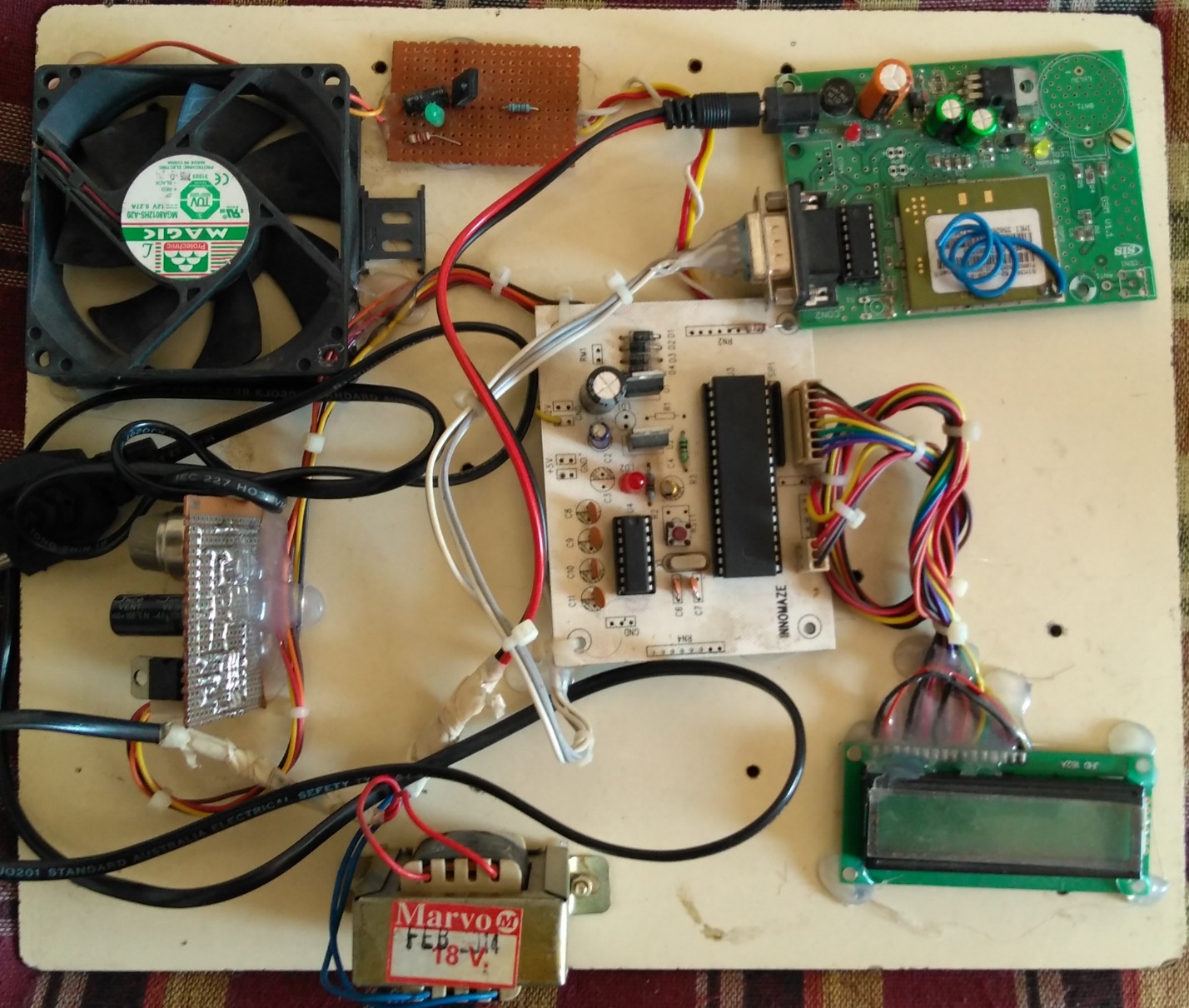
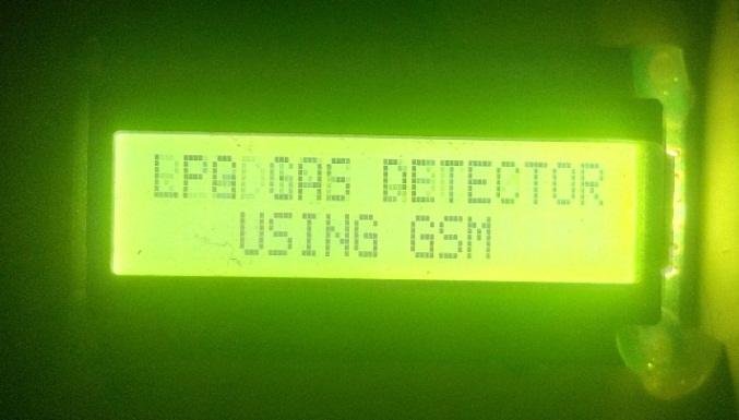
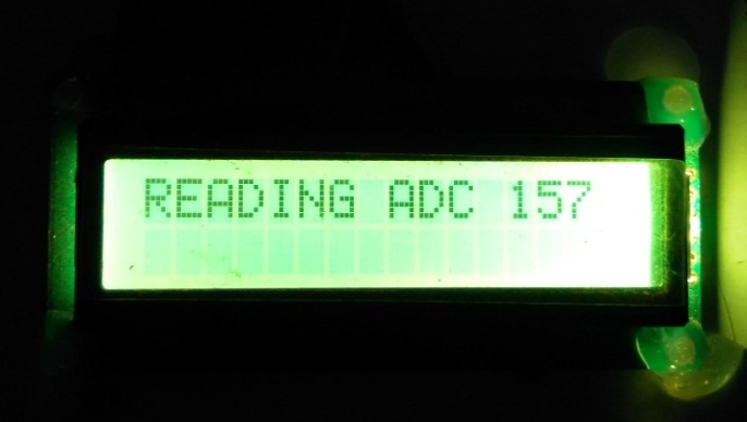
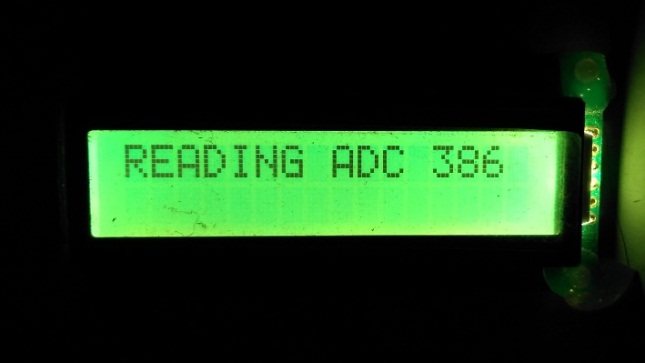
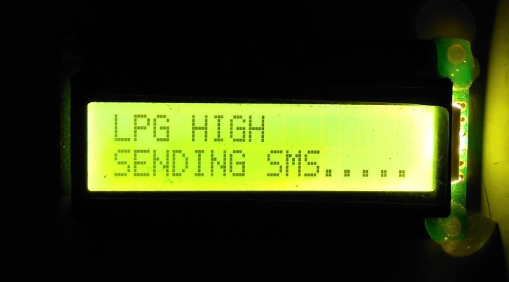
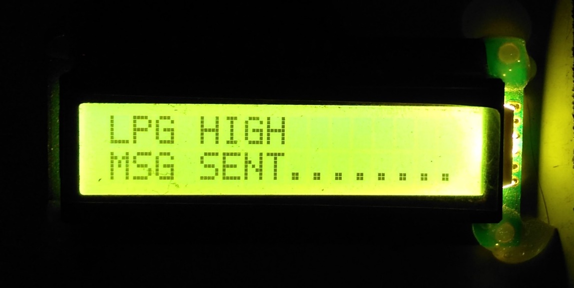
The images below show the working and the output of the project, both in ideal state and in case it detected a leakage.
CHAPTER-6
CONCLUSION AND FUTURE SCOPE
6.1Conclusion
These days, most couples leave for work at a young hour in the morning and get back just at night. A great many people additionally need to go to different urban areas for their work. When they are away, their home is vacant. In this way case like spillage of LPG and blasts may happen. Our nation, India has numerous such cases and as yet going climbing step by step. The based arrangement is to create home-security framework utilizing a remote to protect your home from such mishaps and empower you to work in peace.
In light of the occasions over, the venture can create to make our home secure and safe. Along these lines, this venture is to plan and build up a home-security framework that can give security against gas spill and other crisis circumstances by alert through informing and calling the property holder as there is something suspicious at home. Today there are numerous remote home-security caution frameworks accessible in the market. Some are intended for high security level assurance and some are essential sort. The majority of the caution frameworks are exceptionally costly and in this manner not moderate to poor people or white collar class families. A few frameworks which are less expensive don’t give solid components like status checking. To furnish the general population with a financially savvy remote security framework, it is imperative to outline a minimal effort framework with cutting edge highlights which likewise helps in declining the mishap rate.The uniqueness of the project is that it not only alerts the surroundings through siren but also alerts the remote user through GSM. A mobile number or a landline number can be fixed to it.
6.2 Future Scope
Detection of the gas leakage is the primary concern of the project, since it triggers a fire accident. But, an explosion might occur in other cases due to the random factors like an incredible increase in the temperature and pressure in the surroundings of the gas system. This might happen due to a fire accident in its surroundings, which lack a proper detection and alerting system.
As many as 8 sensors can be connected to the AT89S52. Hence, in addition to the MQ-5 gas sensor, one may connect the other sensors like the temperature, pressure and fire detecting sensors compromising with the cost and program simplicity. But this results in the advanced features with utmost achievable reliability.
6.3 Bibliography
Books Referred:
Muhammad Ali Mazidi andJanice Gillispie Mazidi, “The 8051 Micro controller and Embedded Systems”, Pearson Education, 2nd edition, 2009.
Kenneth J. Ayala, “The 8051 Micro controller Architecture, Programming & Applications”, Cengage Learning, 3rd edition, 2011.
David E. Simon. “An Embedded Software Primer”, Pearson Education, 2009
V. K. Mehtha, “Principles of Electronics”, published by S. Chand group, 3rd edition, 2003.
Simon Haykin, “Communication Systems”.
Theodre S Rapport, “Wireless Communications”, Pearson Education, 2007.
DATASHEETS


You have to be 100% sure of the quality of your product to give a money-back guarantee. This describes us perfectly. Make sure that this guarantee is totally transparent.
Read moreEach paper is composed from scratch, according to your instructions. It is then checked by our plagiarism-detection software. There is no gap where plagiarism could squeeze in.
Read moreThanks to our free revisions, there is no way for you to be unsatisfied. We will work on your paper until you are completely happy with the result.
Read moreYour email is safe, as we store it according to international data protection rules. Your bank details are secure, as we use only reliable payment systems.
Read moreBy sending us your money, you buy the service we provide. Check out our terms and conditions if you prefer business talks to be laid out in official language.
Read more